Jason Postlaunch Satellite Characteristics for POD activities
Satellite reference system
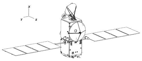
The reference axes for Jason are similar in orientation to those of TOPEX/Poseidon. The X axis is along the satellite's main direction, pointing from the attachment ring towards the radiometer antenna. The Y axis is transverse, along the solar panels. The Z axis is radial, pointing towards the Earth.
The reference point is at the center of the attachment ring.
Mass and center of mass
The fuel tanks on Jason have been designed and aligned so that the center of mass of the spacecraft as a whole only moves along the X direction during the satellite's life in orbit. By construction this is the X axis, so that the Y and Z coordinates of the center of mass in the spacecraft frame are always zero.
The table below gives the spacecraft mass first after deployment in orbit, then once 8 kg of hydrazine have been used. The expected cost of the station acquisition is around 5 to 6 kg. Both the spacecraft mass and center of mass location will be updated once in orbit, and throughout the life of the mission.
| Mass (kg) | X center of mass (mm) | |
| after deployment in orbit | 489.1 | 935 |
| minus 8 kg of hydrazine | 481.1 | 942 |
This mass and center of mass are for the whole spacecraft, including the solar panels. For information, the solar panels' mass is 42.4 kg, and their center of mass is located on the X axis at 855 mm.
Attitude control
The attitude control law for Jason is identical to that of Topex/Poseidon. Its yaw motion is designed to keep the proper orientation of the solar panel rotation axis. Its pitch motion keeps the altimeter antenna pointed perpendicular to the reference ellipsoid.
When the angle of the Sun over the orbit plane is smaller than 15 degrees, the yaw rotations are stopped and the satellite is placed in fixed yaw. When the Sun crosses the orbit plane, the satellite reverses itself (flip).
Contrary to Topex/Poseidon, the transition between fixed and sinusoidal yaw modes for Jason should occur at well defined times. For each day of the cycle, there is an identified orbit when the transition can occur, close to the sub Solar point in order to minimize rotations. Thus it should be possible to predict when these tansitions will occur. In the short term, we will provide an Satellite Attitude Events File similar to the one for Topex/Poseidon. There might be a possibility to also provide quaternions in the future.
Macro-models
Macro-models for Jason have been derived from a detailed satellite description file provided by the manufacturer. These data were used to compute a micro-model for the spacecraft central body. Accelerations due to solar radiation were computed for all possible incoming light directions using this model. A simplified 6-face box model was then optimally adjusted to reproduce these accelerations as accurately as possible. As the box model was adjusted to the whole set of incoming directions it can be used for direct solar radiation pressure computation as well as for albedo computation.
The product of the surface by the optical coefficient is the only factor that matters in the computation of the accelerations. We used this degree of freedom to set the areas of the box model to the actual projected surfaces of the satellite, instead of applying the usual normalization which sets the sum of coefficients to 1. The advantage of this approach is that the same physical model can be used for drag and radiation forces. If your software requires normalized coefficients, just resize the surfaces!
Care was taken to include all effects in the model. In particular, the visible model takes into account the fact that the energy absorbed by the thermal blanket is completely reradiated at infrared wavelengths (it does not contribute to heating up the spacecraft). The visible properties of the blanket were modified to account for this effect. Additional details will be provided in a technical note.
For the solar arrays, SA+ corresponds to the face turned toward the Sun.
| Jason visible | ||||||||
surfaces | X+ | X- | Y+ | Y- | Z+ | Z- | SA+ | SA- |
area | 1.65 | 1.65 | 3.0 | 3.0 | 3.1 | 3.1 | 9.8 | 9.8 |
specular ref. | 0.436 | 0.434 | 0.357 | 0.321 | 0.240 | 0.318 | 0.344 | 0.004 |
diffuse ref. | 0.209 | 0.215 | 0.375 | 0.400 | 0.402 | 0.370 | 0.006 | 0.298 |
absorbed ref. | -0.001 | 0.005 | 0.271 | 0.308 | 0.330 | 0.267 | 0.647 | 0.697 |
| Jason infra-red | ||||||||
surfaces | X+ | X- | Y+ | Y- | Z+ | Z- | SA+ | SA- |
area | 1.65 | 1.65 | 3.0 | 3.0 | 3.1 | 3.1 | 9.8 | 9.8 |
specular ref. | 0.425 | 0.408 | 0.334 | 0.274 | 0.236 | 0.298 | 0.097 | 0.035 |
diffuse ref. | 0.178 | 0.186 | 0.342 | 0.369 | 0.382 | 0.336 | 0.098 | 0.035 |
absorbed ref. | -0.026 | -0.012 | 0.249 | 0.297 | 0.309 | 0.240 | 0.803 | 0.931 |
In order to take in account the thermal emissivity in routine operation, resulting from the energy dissipated by the various instruments and radiated through the radiators, one has to add a constant bias force fixed with respect to the satellite's frame
| emissivity | radiated power (W) | force (µN) |
| Xs | 40 | -0.09 |
| Ys | 80 | -0.18 |
| Zs | 0-8 | 0.0 |
Instruments phase centers
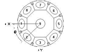
The phase centers of the various instruments of Jason are given below in the satellite frame
| X (mm) | Y (mm) | Z (mm) | |
| Altimeter | 1616.0 | 0.0 | 477.5 |
| Doris 2GHz | 1171.0 | - 598.0 | 1027.0 |
| Doris 400 MHz | 1171.0 | - 598.0 | 859.0 |
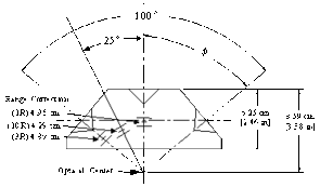
| LRA (optical center) | 1171.0 | 598.0 | 682.8 |
| GPS 1 - L1 | 2408.0 | 219.7 | -537.2 |
| GPS 1 - L2 | 2420.1 | 220.7 | -558.3 |
| GPS 2 - L1 | 2408.0 | -219.7 | -537.1 |
| GPS 2 - L2 | 2420.2 | -220.8 | -558.5 |
Doris
Note that for Doris, the export data is referenced to the 2 GHz frequency (the position of the 400 MHz phase center is not required). The two Doris receivers are connected to the same antenna.
GPS
For the Turbo-Rogue GPS Space Receiver, the two receivers are connected to independant antennas. The receiver that will be turned-on after launch is the 2. The GPS antennas are tilted with respect to the satellite's axes. The spacecraft relative phase locations are thus obtained by applying a rotation to the phase center positions measured relative to the antenna.
The following tables give the reference points of the GPS antennas with respect to the spacecraft, the rotation matrices going from the satellite's frame to the antenna frame, and the location of the phase centers in antenna frame.
| reference points | X (mm) | Y (mm) | Z (mm) |
| GPS 1 | 2370.5 | 216.4 | -472.1 |
| GPS 2 | 2370.5 | -216.4 | -472.1 |
rotation matrix from satellite frame to antenna frame for GPS 1
| 0.867 | -0.025 | 0.497 |
| 0.000 | -0.999 | -0.050 |
| 0.498 | 0.044 | -0.866 |
rotation matrix from satellite frame to antenna frame for GPS 2
| 0.867 | 0.025 | 0.497 |
| 0.000 | -0.999 | 0.050 |
| 0.498 | -0.044 | -0.866 |
antenna phase center in antenna frame (along the antenna axis)
| Z (mm) | |
| GPS 1 L1 | 75.2 |
| GPS 1 L2 | 99.5 |
| GPS 2 L1 | 75.1 |
| GPS 2 L2 | 99.8 |
LRA
If you experience any problem processing the Jason data or understanding the spacecraft description, please contact:
CNES Precise Orbit Determination Group
18 avenue E. Belin
31401 TOULOUSE Cedex 4
France
