


SWIM radar
The SWIM instrument is a real-aperture radar (RAR) system at Ku-band (13.575 GHz), pointing at 6 incidence angles between 0 and 10° (with a step of 2°) with a rotating beam antenna over 360°.
The nadir looking is used in a way similar to other radar-altimeters for estimating wind speed and significant wave height. The off-nadir looking observations are used to measure the directional ocean wave spectra, and statistics of wave slopes.
The following videos show an overview of the operation of the instrument:
SWIM (Surface Waves Investigation and Monitoring instrument)
SWIM is a new CNES Ku-band radar instrument, manufactured by TAS (Thales Alenia Space), Toulouse, France; it is based on the technology of a spaceborne radar altimeter. SWIM is the first ever space radar concept that is mainly dedicated to the measurement of ocean waves directional spectra and surface wind velocities through multi-azimuth and multi-incidence observations. Orbiting on a 519 km sun-synchronous orbit, its multiple Ku-band (13.575 GHz) beams illuminating from nadir to 10º incidence and scanning the whole azimuth angles (0-360º) provide with a 180 km wide swath and a quasi global coverage of the planet between the latitudes of ±80º.Such a wide range of observations, requiring high-range resolution (about 20 m on the ground), have led to design an instrument whose architecture and technology goes beyond what has been done on altimeter and scatterometer implementations. The global coverage and the reduction of telemetry budgets have required performing onboard range compression. The variety of signals at different incidences, the impact of the complex moving geometry of observation and the required real-time signal processing have led to propose onboard complete digital range compression on backscattered 320 MHz bandwidth signals. The design of the onboard compression and processing resulted from a trade-off between the instrument high level performances required, the needed correction for geometrical effects such as range migrations and performance of the acquisition and tracking loops.The multi-azimuth multi-incidence observations requirements have led to design an ambitious antenna subsystem that rotates at 5.6 rpm while transmitting six high power RF signals towards tunable directions. This configuration allows a 180 km wide swath and a quasi global coverage of the planet between the latitudes of ±80º.The real aperture radar SWIM instrument is composed of :
- Ku-band (320 MHz bandwidth)
- On-board digital processing
- 6 distinct beams between nadir and 10° incidence
- Rotating antenna at 5.6 complete rotations/min.
The RF (Radio Frequency) radiating performances have to be warranted for each of the 6 beams on the 360º rotation under flight conditions. In particular, the antenna subsystem shall ensure the pointing stability of each beam under rotation throughout the 3 years of nominal mission life. The antenna design shall also minimize the impact of mechanical and thermal environments on its critical components (active equipments).
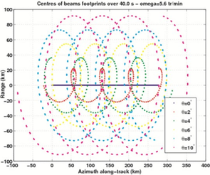
Observation configuration
For an orbit altitude of 500 km, the footprint is about 18 km x 18 km. This footprint sweeps a pseudo-circle with a diameter ranging from 18 to 90 km for incidence angles ranging from 2 to 10°.
SWIM antenna assembly
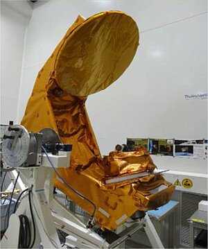
The antenna design, operating in transmit and receive modes, features an offset reflector geometry combined with the RFA (Rotating Feed Assembly), including 6 horns and a switch matrix, allowing to switch the RF signal between each horn. The RF rotary joint, which is part of the complex RMA (Rotary Mechanism Assembly), ensures the interface between the fixed RF part and the rotating one. A stepper motor allows the precise rotation of the RFA. The rotating RFA is electrically fed and controlled using a collector, the RMA is aligned by a set of bearings.
A calibration probe is implemented close to the reflector to be able to calibrate each of the 6 beams in flight conditions. The SWIM antenna is electrically fed and commanded by a dedicated APCE (Antenna Power and Command Equipment).
The multibeam SWIM antenna is comprised of the following elements :
- A composite mechanical structure supporting the reflector and the rotating feed
- A rotating feed including: RMA (Rotary Mechanism Assembly) composed of a RF rotary joint, a motor, a collector, two bearings, and a HARM (Hold And Release Mechanism) system and RFA (Rotary Feed Assembly) including a switch matrix in ferrite technology with associated drivers and 6 horns with associated mechanical plate
- A passive calibration system allowing to calibrate in flight conditions the 6 antenna beams
- An antenna thermal control device.
RFA (Rotary Feed Assembly): The RFA is composed of 6 horns, a switch matrix and a mechanical interface structure. The RFA is rotating at 6 rpm (revolutions per minute) in the instrument nominal operating mode. To obtain the optimal performance for each beam, three different designs have been optimized for the horns. The location of the horns on the rotating plate has been optimized to comply with the beam pointing requirement as well as the center of gravity, inertia, and the interfaces with the switch matrix.
The switch matrix allows to switch the RF signal between the 6 beams - which operate in transmit and receive modes. The matrix includes 5 ferrite switches with electronic driver devices. The ferrite switches are RF interconnected by WR62 waveguide junctions. The switch locations and the routing of the waveguide junctions have been enhanced to minimize the RF losses and to be compliant with the rotating plate mechanical interfaces.
RMA (Rotary Mechanism Assembly). The RMA is developed in the frame of the CNES/TAS SWIM instrument. It is a high lifetime mechanism enabling the holding, the release and the rotation of 6 RF beams integrated on an antenna structure at 5,6 rpm continuously during 3 years (qualification needs: 13,6 millions of turns). This mechanism is composed of a rotary for the rotation (with a RF joint and a slip-ring for digital commands in particular), and by 3 HRMs for the holding and the release. The RMA supports the following functions :
- Stowage of the RFA during the launch sequence
- Rotate the RFA with accuracy and stability
- Provide the RFA angular positioning
- Transfer the feed and command signals from the APCE to the switch matrix
- Transfer the RF signal between instrument RF unit and RFA
- Transfer the electrical grounding to RFA.
- The RMA is composed of the following elements:
- A stepper motor
- A collector for electrical signal transmission
- The RF rotary joint
- Two bearings
- A set of 3 HARMs (Hold and Release Mechanisms)
- A set of mechanical interfaces.
Mechanical and thermal design of RFA and RMA: The mechanical and thermal designs have been optimized to limit the constraints on the RFA and RMA devices.
SWIM antenna RF performance: One of the most critical RF performance parameters to optimize was the beam aperture evolution minimization (aperture evolution lower than 10%) For this particular beam, strongly depointed from nadir, the unsymmetrical side lobe effects have been minimized.
The worst case RF performance analysis has met compliance with the RF antenna requirements.
Further information:
- The SWIM radar on the Space Scientific Mission website.