


Jason system overview and status
P. Escudier (CNES, France), G. Kunstmann (NASA/JPL, USA), F. Parisot (CNES, France), R. Boain (NASA/JPL, USA), T. Lafon (CNES, France), P. Hoze (CNES, France), S. Kaki (NASA/JPL, USA)
This paper briefly recalls the overall context of the joint NASA/CNES Jason-1 mission, its objectives and fundamental similarities and differences with respect to TOPEX/POSEIDON, its highly successful predecessor. It then focuses on the development and qualification status of the satellite, and describes the instruments and short-term future activities leading up to the launch towards the end of 2000.
In December 1996, the Centre National d'Etudes Spatiales (CNES) in France and the National Aeronautics and Space Administration (NASA) in the United States formally agreed in a Memorandum of Understanding (MOU) to jointly participate in a space mission to design, build, deploy, and operate a satellite to continue the collection of sea-surface elevation measurements originally begun by the TOPEX/POSEIDON mission. TOPEX/POSEIDON, launched in August 1992, was the first such mission in a worldwide effort to study and describe global ocean dynamics and their relationship to the Earth's environment and climate change. The unprecedented success of TOPEX/POSEIDON led mission planners to recognize the need to sustain the high-accuracy measurements of sea surface elevation in order to integrate this information into ocean and climate models for long-term climate monitoring and prediction.
The Jason-1 follow-on mission is also an international cooperation effort. Where it differs from TOPEX/POSEIDON is in the division of responsibilities between CNES and NASA, with an almost complete reversal of roles. Further, Jason will build on the success of TOPEX/POSEIDON to take satellite altimetry to new levels of accuracy that need no longer be considered experimental in nature. In addition, this mission must be accomplished in a much more restrictive fiscal environment requiring both CNES and NASA to limit overall mission costs.
To provide a valuable successor to TOPEX/POSEIDON in this constrained funding context, both agencies have decided to share their participation. NASA is providing the launcher, the routine operational ground control segment, the radiometer, a GPS for complementing precise orbit determination and a laser retroreflector array. CNES is providing the satellite, the radar altimeter, DORIS for nominal precise orbit determination and the control ground segment used during the early phase of the mission. Each agency is also providing a mission ground segment.
More compact electronics packaging has enabled a tremendous reduction in the required satellite resources. For example, the overall mass of the Jason satellite will be less than 500 kg (2400 kg for the TOPEX satellite).
The Jason System
The Jason Name
Jason was the leader of the celebrated quest by the Argonauts to recover the Golden Fleece, guarded by a dragon at Colchis on the Black Sea. Jason picked 50 volunteers and on board Argo, the first ship ever built, after many years of effort sailing the Mediterranean and the Black Sea, Jason and the Argonauts finally recovered the Golden Fleece.
System Constraints
NASA and CNES headquarters have imposed the following constraints on the Jason-1 project to bound and scale the effort of defining the mission and project system:
- The Memorandum of Understanding co-signed by the CNES Chairman and NASA Administrator defining the general responsibilities of the parties and the terms and conditions under which they have agreed to cooperate on Jason-1.
- The use of the generic PROTEUS satellite bus, developed in partnership with Alcatel Space Industries with minimal adaptations. Jason-1 is the first satellite to use this bus.
- The development of a new set of instruments, obviously largely inherited from TOPEX/POSEIDON but aiming to reduce mass and power consumption through new technologies, and thus increase availability and facilitate operations.
- The use of the PROTEUS generic ground segment (control center and one earth terminal) adapted to Jason.
- The use of the Delta launch vehicle with a co-manifest partner, TIMED.
- The use of a multi-mission center (SSALTO) operating for Jason, DORIS /Spot and DORIS/EnviSat and processing and distributing EnviSat altimeter data as a CNES mission center.
- The re-use of the TOPEX/POSEIDON ground system (TGS) as a baseline for developing the Jason Project Operation Control Center (POCC)
- The launch date, then set for May 18, 2000.
Jason launcher and launch support
NASA is providing a Delta II (7920-10) vehicle to launch the Jason-1 satellite as a co-manifested partner with the TIMED satellite. The Delta launcher will be fitted with a newly developed Dual Payload Attach Fitting (DPAF) to accommodate the two spacecraft within the fairing. The DPAF is the load-bearing structure to which each spacecraft is attached and secured during launch. Jason-1 is physically attached to the top of the DPAF and is the first payload to be separated after injection into the Jason-1 orbit. Once Jason-1 is deployed, the Delta performs propulsive maneuvers to change the orbit, after which it then deploys the TIMED spacecraft.
In order to achieve the 66°-inclined satellite orbit, Jason-1 will be launched from Vandenberg Air Force Base (VAFB), Delta launch Pad (Space Launch Complex - 2W), California. Prior to launch, the fully integrated Jason-1 satellite will be transported from Cannes, France, to VAFB by air. Pre-launch ground operations will be accomplished at the Spaceport Systems International (SSI) processing facilities, in a processing bay adjacent to the TIMED spacecraft processing bay. Just prior to transportation to the launch pad, the Jason-1 satellite will be fuelled and then mated to the upper adapter on the DPAF, completing the stackup of the two spacecraft. This operation will also take place at SSI. Overall, the launch campaign for Jason-1 is expected to last no more than seven weeks from arrival at VAFB to launch, including mating to the DPAF and joint operations with TIMED.
The Delta lifts the satellite to an orbit biased approximately 10 km below the operational orbit altitude. After a sequence of maneuvers to phase and raise the orbit altitude, the Jason-1 satellite will assume a position relative to the TOPEX/POSEIDON satellite such that each satellite makes measurements of the same point on the surface within approximately one minute of each other. The two then begin a period of formation flying to cross-calibrate the altimeters and validate the measurements taken by Jason-1. Eventually, TOPEX/POSEIDON will use its propulsion system to maneuver to a different position relative to Jason-1 and continue complementary measurements for the rest of its useful mission life.
Jason Project milestones
| ||||||||||||||||||||||||||||||
| Table 1: Jason project milestones |
The Jason Satellite
Characteristics and performance
| |||||||||||||||||||||||||||||||
| Table 2: TOPEX/POSEIDON - Jason-1 comparison | |||||||||||||||||||||||||||||||
Table 2 shows clearly that integration of payload technology combined with improved "conventional" platform supporting functions plays a leading role in reducing overall resources budgets. The Jason satellite uses the standard multi-purpose PROTEUS bus. A dedicated Payload Instrument Module (PIM) has been built for this mission to accommodate the instruments. The payload module has the same structural definition as the platform. The design is such that the payload is thermally decoupled from the platform. The Jason satellite is a protoflight model. The Platform has already been successfully qualified on a structural mock-up (static, sine, acoustic vibration, shock and solar vacuum tests). The Jason satellite has a design lifetime of three years but the components are built to withstand the expected radiation environment for five years (1336-km orbit). Consumables are also sized for a five-year mission. The maximum power consumption is about 435 W. The overall satellite mass is less than 500 kg with full loading of hydrazine (28 kg) and the satellite is about 3.4 meters high. Due to the high orbit nodal rate (2° per day), the satellite performs yaw-steering attitude control maneuvers to provide the solar array with proper solar illumination. The payload science data rate of 25 kbps is continuously stored in the onboard mass memory and is downloaded each time a terminal is within view at 613 kbits/s. | ||||||||||||||||||||||||
| ||||||||||||||||||||||||
| Table 3: Jason performance |
Mission instruments
The nominal Jason payload consists of:
- a dual-frequency altimeter named POSEIDON-2 and its associated antenna;
- a three-frequency radiometer and its antenna named Jason Microwave Radiometer (JMR);
- the DORIS onboard package, comprising:
- the Doppler receiver (MVR)
- the ultra-stable oscillator (USO)
- the associated antenna
- a laser retroreflector array (LRA);
- a GPS space receiver (TRSR).
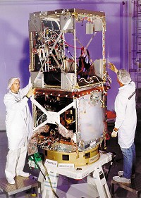
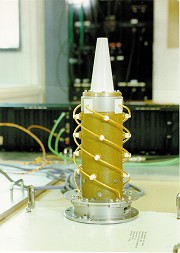
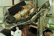
Figure 1: Jason-1 during integration (copyright Alcatel)
POSEIDON-2
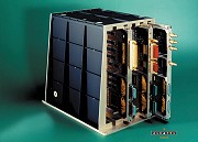
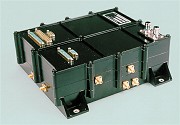
The POSEIDON-2, low-power, low-mass solid-state altimeter, derived from TOPEX/POSEIDON's POSEIDON-1 altimeter, sends radar pulses at two frequencies (13.6 and 5.3 GHz). The C-band channel provides direct ionospheric correction for the primary Ku-band measurement and uses a 1.2-meter antenna on the nadir side of the satellite. The altimeter electronics is configured in four boxes, two processing units and two RF units (nominal and backup). The processing unit includes the digital chirp generator, baseband demodulator, spectrum analyser, instrument control unit and interfaces. The RF unit includes the up-conversion to the Ku and C-band, high-power amplifier (solid state), low-noise amplification of the received echoes and mixing with the reference chirp. The peak output channels are 8 W for the Ku-band and 25 W for the C band.
CNES is the prime contractor for the altimeter and is responsible for achieving the performance levels expressed in the system requirements document. Development and testing of electronic boxes have been subcontracted to Alcatel Space Industries Toulouse (which developed POSEIDON-1). Development and testing of the antenna have been subcontracted to Alcatel Space Industries Cannes.
This altimeter being a new development, an electrical breadboard of the processing unit has been developed. A qualification unit and two flight units of the altimeter (processing unit, RF unit and switch box) have also been manufactured and tested. A subset of the ground support equipment developed by Alcatel (including the waveform simulator) will be used for satellite assembly, integration and test activities.
For the antenna, a recurring model of the Thaicom satellite antenna dish will be used with a specific feed system. An electrical model has been developed and a protoflight model built.
The processing unit electrical model will be used for testing on the satellite electrical test bench.
DORIS
The DORIS receiver is a radio tracking system developed by CNES, using the Doppler shift of ground beacon signals to provide high-precision orbit determination. The onboard package includes the receiver (two boxes in cold redundancy), the ultrastable oscillator (USO 1 and 2 in cold redundancy, housed in a single enclosure providing magnetic shielding), a switch box and an omnidirectional antenna. The DORIS receiver will be a miniaturized version of that scheduled to fly on ENVISAT, with some modifications for the 1553 bus interface. It will provide a dual beacon receiving capability and an onboard real-time function to compute orbit ephemeris data accurate to 1 meter rms (30 cm for the radial component).
The DORIS/Jason onboard package, including the Doppler receiver, USO and antenna, has been subcontracted to Dassault Electronic (now Thomson Detexis) with CEPE for the USO and Starec for the antenna. All of these contractors developed the hardware for DORIS/TOPEX, DORIS/Spot and DORIS/ENVISAT. As for the altimeter, a qualification model and two flight units will be developed for the receiver. The ground support equipment (GSE) used for the satellite assembly, integration and test sequence is developed by Dactem, which built the GSE for the DORIS family. Dactem also developed the DORIS simulator that will be used for testing on the satellite electrical test bench. The antenna, USO and USO shielding are recurring models.
JMR
The Jason Microwave Radiometer (JMR) is a three-frequency microwave radiometer that corrects path delays due to atmospheric water vapor. It has separate channels at 18.7 GHz, 23.8 GHz, and 34.0 GHz. The 23.8 GHz channel is the primary water vapor sensor, the 18.7 GHz channel provides a correction for wind-induced effects in the sea surface background emissions, and the 34.0 GHz channel provides a correction for non-raining clouds. The receivers use microwave monolithic integrated circuits (MMICs) for their high reliability, low power and low mass. As the 23.8 GHz channel is the primary channel, a fully redundant backup channel is provided. Additionally, fully redundant digital control systems, and 1553B interfaces are incorporated.
Design and fabrication of the MMIC receivers was subcontracted to TRW. Fabrication, test, and calibration of the JMR was accomplished at JPL, along with its ground support equipment. A full-up engineering model and the flight unit have been delivered to Alcatel Space Industries.
TRSR
The Turbo Rogue Space Receiver (TRSR) is a Global Positioning System (GPS) receiver developed by the Jet Propulsion Laboratory (JPL) to provide precise orbit determination in post-processing with a radial accuracy of 1-2 cm. The TRSR can continuously track the dual-frequency navigation signals from up to 16 GPS satellites at once. From these signals the instrument acquires measurements of the GPS carrier phase (which can be interpreted as range change) with a precision of about 1 mm and the absolute pseudo-range (defined as the absolute range plus receiver time offset from GPS time) with a precision of about 10 cm. The TRSR will also offer onboard solutions for spacecraft position and time accurate to about 50 m and 150 ns, respectively. The onboard package includes two independent single-string receivers in cold redundancy, each comprising an omnidirectional antenna, low-noise amplifier, crystal oscillator, sampling downconverter, and baseband digital processor communicating through the 1553 bus interface.
Fabrication of the TRSR flight units has been subcontracted to Spectrum Astro Inc of Gilbert, Arizona. Ground support equipment was developed at JPL.
LRA
The Laser Retroreflector Array (LRA) provides a target for laser tracking measurements and is used to calibrate the POD system and the altimeter. The totally passive array will be placed on the nadir face of the satellite. The unit consists of nine quartz corner cubes arrayed as a truncated cone with one in the center and the other eight distributed azimuthally around the cone. The array provides approximately a 100-degree field of view. The Jason-1 LRA was manufactured by ITE Inc., under contract to NASA Goddard Space Flight Center.
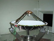
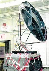
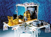
Radiometer (NASA/JPL) - Engineering model during mechanical qualification test. |
|
| ||
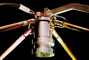
|  |  DORIS antenna (Starec) - Flight model | ||
|
| |||
|
|
|
Satellite Validation, Integration and Test
Satellite electrical, functional and software validation is achieved through the implementation of System Validation Benches on which the mission software and electrical interfaces can be validated.
- BV1 is a software validation bench with simulated equipment (only the Data Handling Unit is representative). A clone of this bench has been developed in order to cope with the tight schedule.
- BV2 is aimed at functional system tests, in open and closed loops with "hardware-in-the-loop" represented by an engineering model for all "intelligent" platform equipment and for all payload instruments. The DHU electrical model is fully representative of the flight unit.
- BVO is used for operations validation.
AOCS flight software is tested on the AOCS test benches for fine tuning of the algorithms by AOCS experts.
Instruments and equipment will be mechanically and electrically integrated in sequence on the satellite, which will then enter a complete protoflight qualification sequence of six months. This sequence starts with the EMC tests, followed by mechanical and thermal tests, and ends with the final set of performance tests including a system test with the ground segment.
After final preparation, the satellite will be flown to Vandenberg Air Force Base where it will be tested (health check only), inspected and fuelled before mating on the DPAF, then erected for launch.
System Progress status (November 99)
Flight models of payload instruments were delivered to Alcatel in June for integration on the satellite, except for the altimeter, which will be integrated later (August timeframe). Performance tests already run on the qualification models for all instruments show full compliance with requirements derived from the high-level science objectives. The project team is thus very confident it will achieve these objectives.
Platform equipment integration has started in parallel with an extensive functional validation using satellite representative tests benches. Here also, the multi-mission requirements for the PROTEUS bus-almost always more stringent than the dedicated Jason-1-mean we are very confident that satellite performance will match and even exceed requirements. This will be demonstrated through the intensive validation and test sequence to be conducted through to the middle of 2000.
After problems were encountered during bench development and validation, it was confirmed in late summer 1999 that the initially scheduled launch date of May 2000 was unrealistic. These problems have impacted validation of flight software, functional validation of the satellite, preparation of the ground segment and finalization of operational procedures. It has also been clearly reaffirmed that the satellite will only be cleared for launch once the system has been fully validated and has proven its ability to control the satellite. Mission planners are now looking to reschedule the launch for the Fall of 2000, but the exact date will be confirmed early next year in the light of progress achieved in satellite integration and validation.
Both space agencies and their industrial partners and contractors have made a huge effort to meet the very tight system schedule, which has been one of the driving factors throughout the development phase and will certainly remain the major challenge of the upcoming integration and test phases. Nevertheless, achievement of performance levels to guarantee that the product meets users’ needs remains the overriding concern.
News
 Archives .
- Aviso Newsletter .
- Newsletter 1 .
- Newsletter 2 .
- Newsletter 3 .
- Newsletter 4 .
- Newsletter 5 .
- Newsletter 6.
- Newsletter 7 .
- Jason-1, after T/P.
- Jason system overview and status.
- Ssalto, new ground segment.
- Review of 1999 and future AVISO activities.
- Jason-1 Calibration/Validation.
- Absolute altimeter calibration in Corsica.
- AVISO CALVAL Activities.
- Multi-variate assimilation to initialize El Niño predictions.
- Investigation at regional scales of sea level variability.
- Assimilating TOPEX/POSEIDON data to better understand Warm Pool replenishment and depletion.
- Further details of the 1997-98 El Niño.
- TOPEX/POSEIDON and TAO: Comparative simulation.
- Newsletter 8.
- Newsletter 9.
- Newsletter 10.
- Search.
- Front-page news.
- Image of the month .
- Operational news and status .